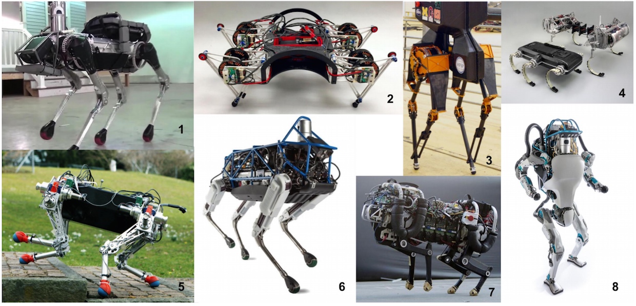
Mobile robots are a blanket category of robots that are capable of locomotion via different strategies. They have been evolving and several new locomotion strategies have been developed. Wheeled mobile robots are one of the first ones developed and been used consistently for long. Several other motion techniques are biologically inspired mechanisms. Quadrupeds, bipeds and hexapods are among few of the most used designs. Bipeds and quadrupeds like Agility Robotics’ Cassie and Boston Dynamics’ Spot Mini are the commercially available versions of these robots. The industry highly appreciates such intricate designs.
While biologically inspired designs are very agile and well suitable for inaccessible areas with uneven terrain or varying climate, wheeled robots have been continuously deployed in flat terrain settings. Wheeled mobile robots are the spearheads of the warehouses, security/surveillance robots and recently found applications in delivery robots as well. Several wheeled robots with enhanced agility like the segways, belt drives and multi-wheel custom designs also exist but have limited scope. All kinds of underwater, amphibious and aerial robots can also be considered as mobile robots, but for the sake of exclusivity, mobile robots refer to terrestrial robots in this article.
The scope of this article is to discuss the kinematics of wheeled mobile robots and provide some insights into the complex kinematics of a few biologically inspired mobile robots.

Introduction
Mobile robots are largely selected depending on stability, surface contact characteristics and environment type. Dynamic or static stability is dependent on the robot’s center of gravity, terrain inclination and flatness, contact points and actuator power. Nature of the surface (hard ground, grass, indoor wooden floor, rocky terrain, deformable surface, snow) and reaction force, friction with the ground and size of contact with the ground decide the applicability of a particular type of robot.
Wheeled mobile robots have different designs with varying degrees of freedom, mobility possibilities and terrain requirements. Wheeled robots are usually frowned upon due to their limited adaptability towards different terrains. Conventional wheeled mobile robots are also unable to traverse through stairs, terrain with variable friction coefficients and uneven terrain. However, the wheeled robot applications far outnumber the other mechanisms due to the sheer volume of possibilities. Wheel robots are easy to develop and deploy due to their simplified kinematics, minimal dynamics and very few degrees of freedom. They are most suitable robots for flat surfaces, the most common application terrain.
Biologically-inspired mobile robots are challenging to build from mechanical design, feasibility and stability perspective. However, legged robots like bipeds and quadrupeds have several advantages like adaptability to the terrain, high maneuverability and ability to manipulate the objects in the environment. High degrees of freedom, typically 12 (6 in each leg) for a biped or 16 in a quadruped make the kinematics and control difficult but provide very agile and dexterous motion at the same time. Static and dynamic stability requirements for 2, 4 or 6 legged robots differ due to different configuration of the center of gravity and convex hulls.
Wheeled Mobile Robots
As mentioned, despite several limitations, the simplicity and large scope of applications make wheeled robots the most favorable mobile robots. There are four basic types of wheels - standard axle wheel, mecannum or swedish wheel, omnidirectional directional and castor/spherical wheels. Wheeled robots use these wheels in different configurations to form two categories of wheeled drives, holonomic and non-holonomic drives.
Holonomic drive robots are such that their constraints are all integrable to position values. In simpler terms, the number of controllable degrees of freedom of the robot is equal to the total number of degrees of freedom. Mecannum and omni wheel drive robots are holonomic drives. They allow the robot to move in any direction instantly without any turning radius or realignment. Often spherical powered wheels can also be used to achieve this behavior but are not efficient mechanisms.
Non-holonomic systems are systems with controllable degrees of freedom less than than the total degrees of freedom. Ackerman, differential and belt drives are all such non-holonomic systems. The motion of the wheels over time cannot be integrated to find the final pose of the robot in such drives. Such mobile robots are incapable of instantaneous movement in a desired direction and always move on a circular trajectory.
Each of these drives has significance in indoor or outdoor applications. The forward and inverse kinematics models of these drives are used to control the motion. Forward kinematics establishes the relationship between the joints/wheels and physical space, while inverse kinematics is needed to convert coordinates on the task space trajectory obtained from motion planning algorithms to joint space instructions for motion control.
For mobile robots, it is safe to restrict motion only in the XY plane with +X protruding out along the robot heading while the Y-axis is perpendicular to the heading as per the right-hand rule. The robot pose is usually represented in its own frame as well as the world frame.

Differential Drive Model
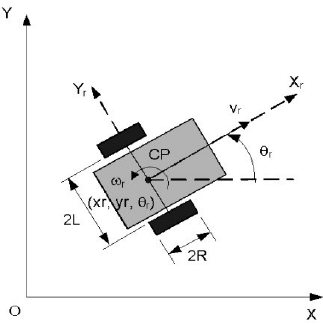
The differential drive is one of the most common drive mechanisms found in delivery or warehouse robots. They have standard geometric wheels and one or more free passive wheels. The robot has a pair of parallel wheels placed on the same axis on either side of the robot body. Relative motion in the wheels on either side makes it move along different curves. Because of the relative movement, it doesn’t need special powered wheels for steering. Instead, it just needs free moving wheels like castor or ball wheels that can align in any direction.
The differential drive can achieve desired orientations without chaning the position, due to zero turn maneuver. However, the poor performance of castor wheels at high speed and poor controllability of the rear wheels and synchronization needs make it not so robust.
There are only certain motion types possible with a differential drive robot.
- If both wheels have the same speed and same direction of rotation, the robot goes in a straight line, either forward or reverse
- If both wheels have the same speed and opposite directions of rotation, the robot does a zero-turn. It is a zero radius turn where the robot rotates about the center of the line joining the two wheels.
- If wheels have unequal speeds, the robot makes a radial turn about an instantaneous center of curvature (ICC).
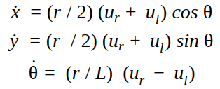
Because the differential drive is a non-holonomic drive, the differential drive kinematics defining its motion are not integrable to the final pose of the robot. The distances traveled by the two individual wheels are not enough and the time sequence of motion is needed to obtain the final robot pose. The linear and angular velocities of the wheels are used to derive the robot position and orientation in the physical space.
Note: A segway is a special case of a differential drive with no freely steered castor/spherical wheel. All the kinematics of a differential drive system are applicable to a segway as well.
Ackerman Drive Model
Ackerman drive is the special steering geometry that solves the problem of wheel slippage and difference in distance to be travelled by the inside and outside wheels while moving along a curve. All commercial vehicles are built on this drive mechanism. This mechanism has a powered pair of rear wheels while the front wheels are used for steering. The front wheels of the drive have a common instantaneous center of rotation that lies on the line joining the two rear wheels. The front wheels’ steering mechanism is called a four-bar linkage and is responsible for effecting different orientations for each of the two wheels.
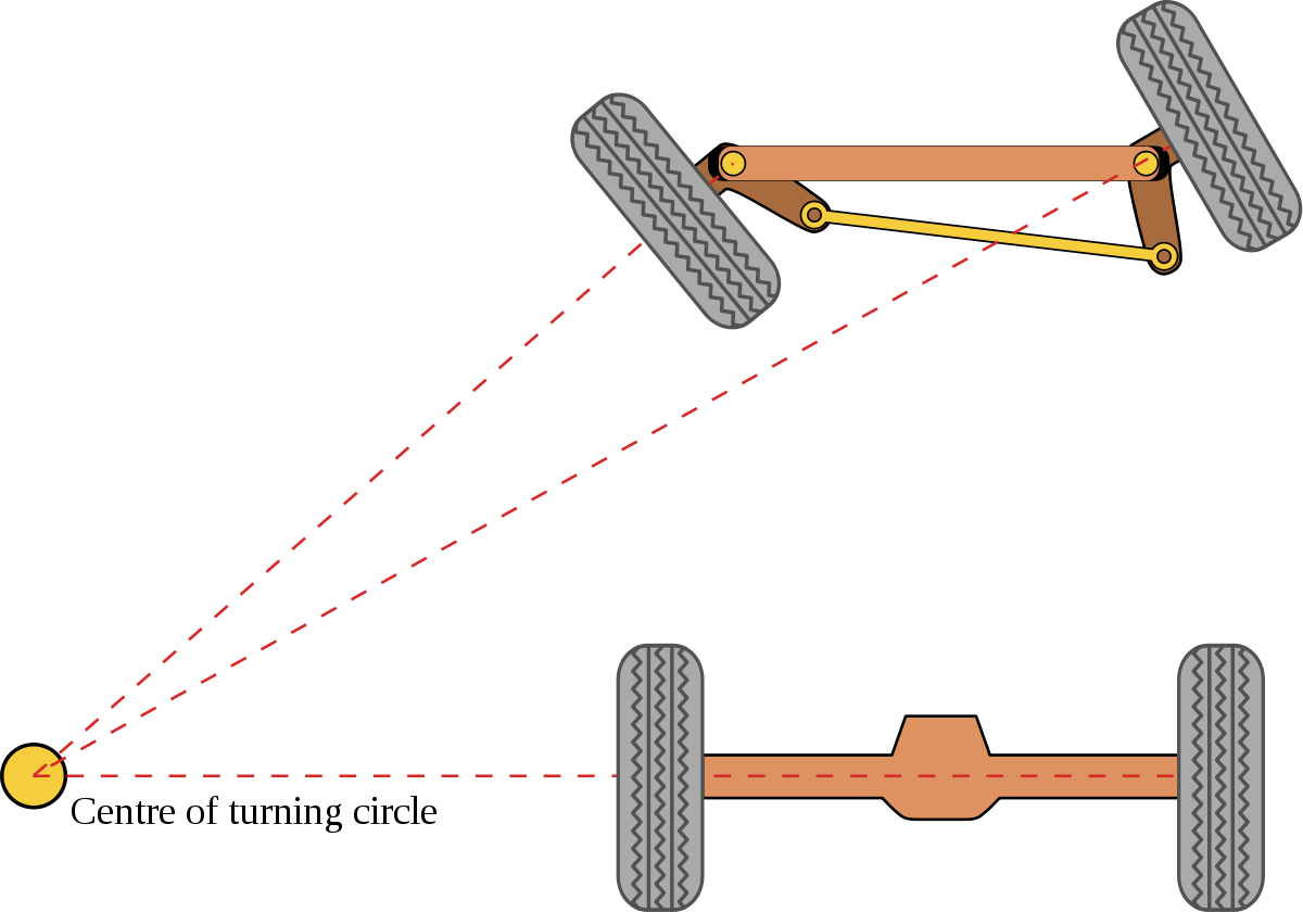
Each of the front wheels in the Ackerman steering has its own pivot but the system is constrained to share a common ICC. An Ackerman steering drive is simplified to a tricycle model. The center of the robot is the point midway on the line joining the two rear wheels.
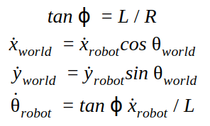
The distance between the robot center and the ICC is called R, the radius and length of the line joining the robot center to the center of the line joining the front wheels is L. The steering angle of the robot is ϕ and it is used to derive the orientations of the individual wheels ϕright and ϕleft (since they are both unique) using basic geometry.
Mecannum Drive Model
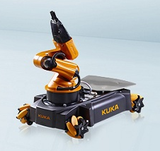
Mecannum wheel drive is the special category of holonomic drive that can drive in any direction, instantaneously. The standard drive has 4 individually powered mecannum wheels. Mecannum wheels have small roller wheels aligned at 45° along the periphery an individual wheels. Different configurations of speeds and directions of the wheels make it possible to travel along specific directions.
The four-wheel mecannum drive is a very complex system where the motion types shown in the image above are valid only if all the wheels have the same speed. Robot hardware is never identical, which means the possibility of having the exact same speed on all four wheels is very low and it introduces several more variables in the kinematics of a mecannum wheel drive.
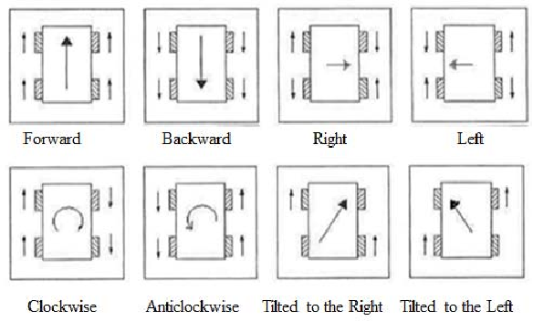
Thus, I decided to spin it out into a new article explaining the kinematics of a mecannum wheel drive at length.
Bioinspired Mobile Robots
While the control of wheeled mobile robots is primarily done in the position space (using velocity inputs) and easy to execute, the dynamics of the system plays an important role in the motion of biologically inspired robots. Motion planning algorithms basically provide the desired path in cartesian coordinates in the global frame and the inverse kinematics solutions of these robots help achieve that motion.
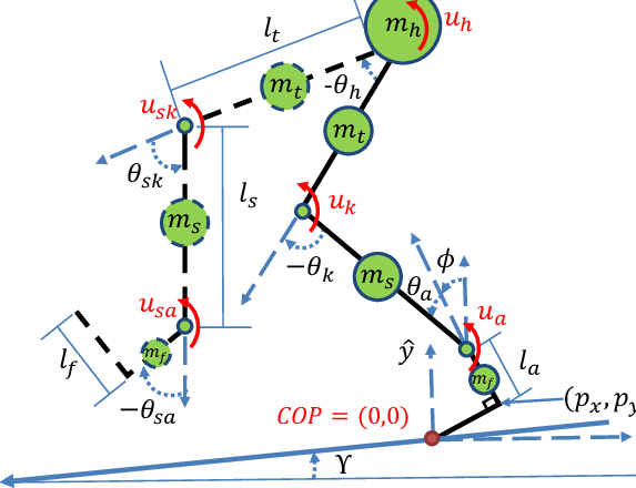
The path definitions for a biped or a quadruped could also individual definitions for each limb. Usually, each robot limb is considered to be an open kinematic chain and IK solutions are computed for the desired pose. These joints are highly constrained in joint position limits making the computations challenging.
One limb of biped could have 6 DOFs or more while that of a quadruped could do with 4 as well. Each of them has its role towards solutions as well as stability of the robot. The orientation of the end of the kinematic chain, the limb toe, is mostly insignificant making the limbs a redundant kinematic chain.
 Model Predictive Control In Robotics - Part I